VESTA-SC
To take pictures of the Deep Sky
or do exposures of about .5 sec in Planetary Shots
!
Dedicated to Stephen Chambers,
UK, alias "Steve"
for his conception which is surprising and
extraordinary!
I also thank Bob for his generous
help for turning my "bad english" legends into understandable ones !
I also warmly recommend his own very nice & helpful
page concerning Steve's
mod !
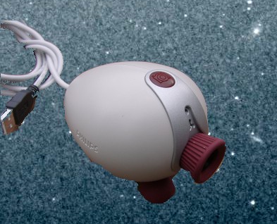
The normal Vesta pro !
VP-SC First light !
|
|
Orion Nebula, Celestron 8", 2 x Reduct 6.3 in ligne
|
See the light pollution where images where taken ! |
|
|
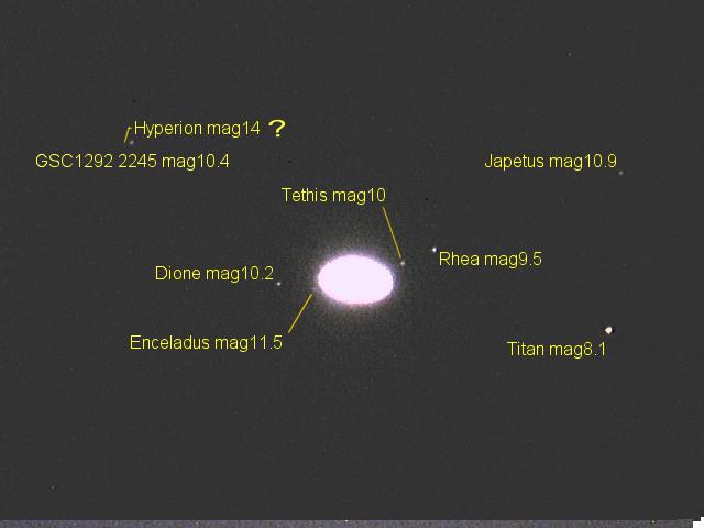
Saturn, C8, Barlow "Powermate 5x" -> Focal 10m |
Same image after treatement with unsharp mask and colors ! |
|
|
Saturne, C8, Barlow 3x Televue -> Focal 6m ! |
Saturn, C8, Barlow 3x Televue -> Focal 6m ! |
The Lyra planetary nebula, |
Saturn, C8 with two 6.3 reducer in line giving F/D=4, |
|
 |
20011012 0157UT
1 Raw 400ms,
|
 |
! Additional pictures for TUCam modification !!
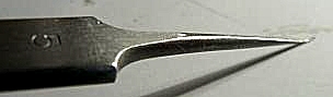
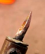
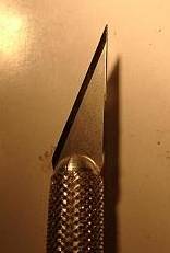
Surgery tools !
Soldering iron should have a thin tip and be low power (25W) |
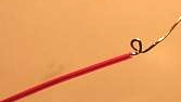
Little wire buckle for soldering on a ic support leg |
1/2 brusselle n°5 bent jewelry pliers to lift pins or twist a buckle of wire |
|
|
 |
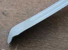
Bend a PC slot protector |
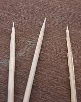
Tooth-pick |
Exacto with (indispensable) new very fine blade |
|
|
|
Wrapping tool |
A pair of thin (fi. iridectomy) scissors |
Hot glue |
 |
(image to come) |
(image to come) |
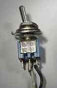
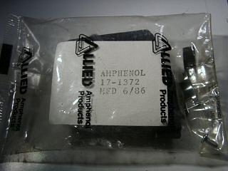
Selected items :
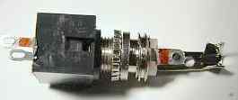
Note: I have just bought stereo jacks with a cut switch. It should make it possible to switch the connection to leg 10 when the male plug of the jack is inserted while also providing the signal coming from pin 2 of the parallel port of the PC, and thus to eliminate the need from a switch ! Later with only 2 of them side by side all the signals from PC parallel port pins 2, 3, 4 & 5 could be brought in to implement the other functions ! Testing to follow!
Stereo jack with internal cut switch to allow the next version of the MOD to not have a switch |
Stereo jack pin side, the pins on the left are used as a cut switch when the male jack is inserted. |
|
|
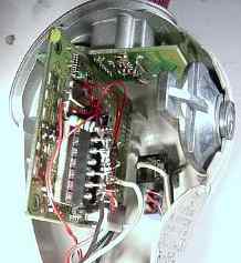
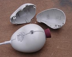
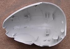
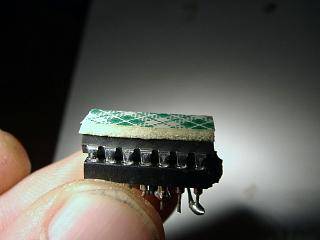
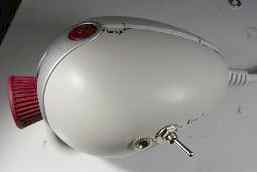
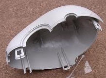
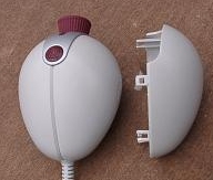
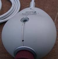
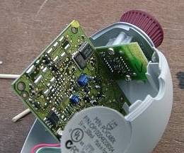
The vesta opened
No ! Nothing to see with Russian dolls! The overview is on the left, the right is the detail of the shells. |
 |
|
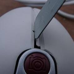
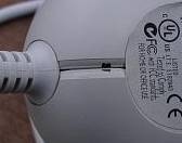
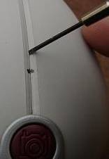
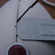
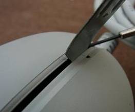
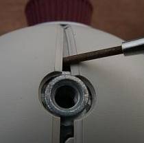
| These images show you how to open the Vesta using a watchmaker's
screwdriver by choosing the right places so you don't break anything ! |
|
 |
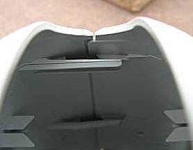
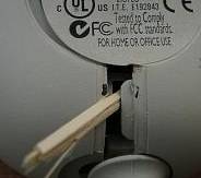
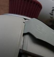
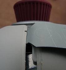
Step by step photos showing how to open without breaking anything !
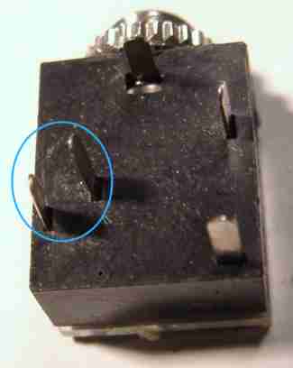
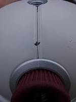
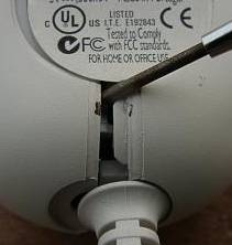
Internal view of spurs |
|
|
|
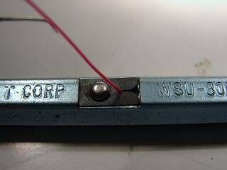
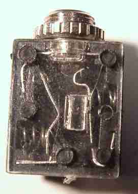
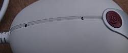
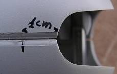
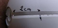
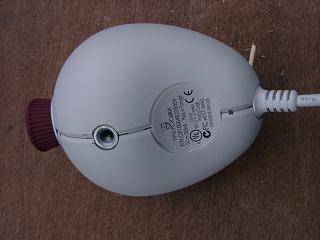
Location of spurs from the outside ! |
|
|
|
|
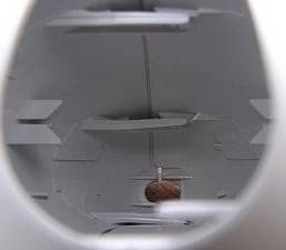
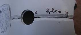
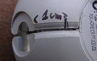
Identification of spurs with precise measurements! |
|
|
|
|
|
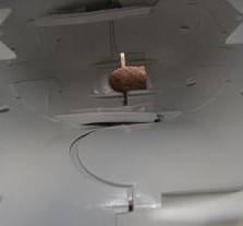
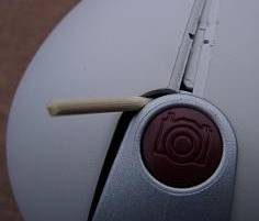
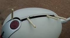
The process of opening The wooden tooth-picks are used to hold it open. Please go slowly! Spurs release with a small brief click using the lever. |
|
|
 |
|
|
|
Turn over Vesta |
|
|
|
|
|
|
|
|
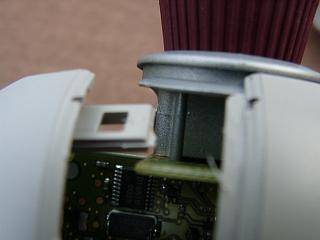
camera opened !
With a little luck no spur is broken !
|
|
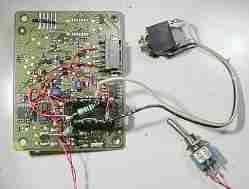
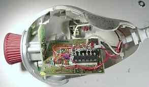
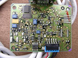
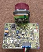
Overview of circuits
| Vesta electronics | Overview on main circuit |
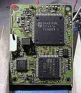
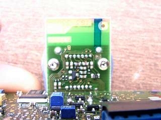
CCD pcb |
|
 |
 |
The last version of the circuit diagram is at :
http://home.clara.net/smunch/wvest2.htm
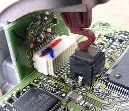
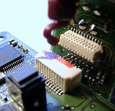
Dismantle by pulling slowly on the CCD PCB!
| Both parts are connected by a white plastic connector | Separate both parts by pulling slowly |
|
|
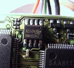
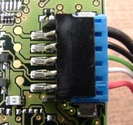
Around USB connector
 |
|
Remove this blue connector to work easily on the circuit. It cannot be plugged back incorrectly. |
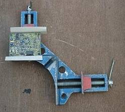
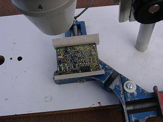
Implementation
The blue part was drilled (large holes) to allow fixation on the underlying wood below the binoculars.The grey cardboard protects the sides of the PCB |
|
|
Sight of the post with the binding screw and its big slice allowing a precise location and a perfect rigidity !
|
|
|
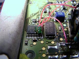
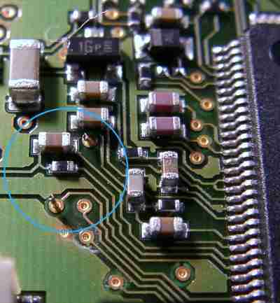
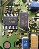
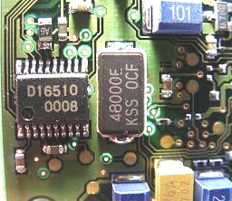
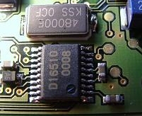
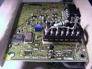
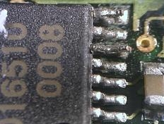
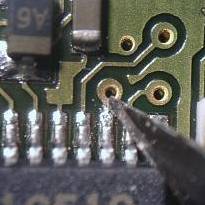
DS16510 and it's environment
 |
|
|
pin 1 is at low right |
 |
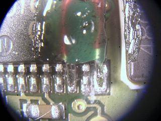
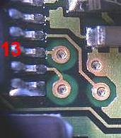
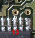
Near pins
8 & 10
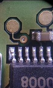
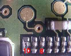
13
Step by step description to make a
Vesta-SC (Steve Chambers)
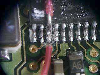
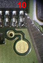
Step 1 : lifting pin 10
Use the point of the Exacto below the pin to cut the solder gradually using small movements, being careful not to slip. |
As the solder is almost completely removed, the pin will start to move very slightly. |
Once the solder is completely cut under the pin, lift the pin to 45° with bent watchmaker's pliers. |
|
|
|
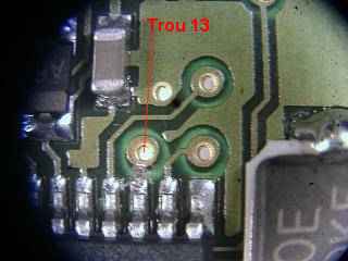
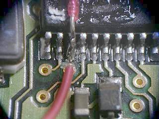
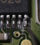
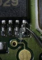
Step 2 : Cutting trace at pin 13
Where to cut |
Work very slowly with the point of the Exacto. ATTENTION there is a trace hidden not far down! Stop as soon as the copper is cut and verify (infinite resistance or no beep) with ohmmeter. |
It's done... clean with Q-Tip & alcool |
|
|
|
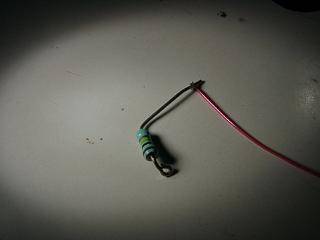
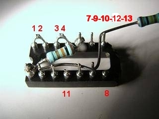
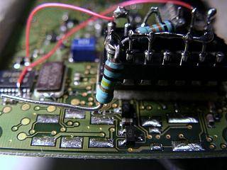
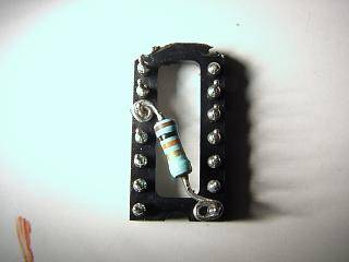
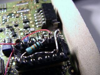
Relax and prepare the 74HC00 circuit
One will use a 2x7 pins chip socket
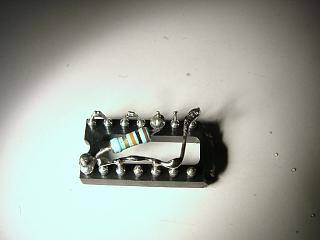
Implementation of the resistor between 5-14 (Brown - black - orange
10Ko)
Prepare the resistor to facilitate soldering |
Position and solder the resistor on the pins of the chip socket. Attention: |
|
|
|
|
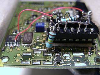
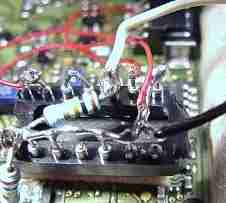
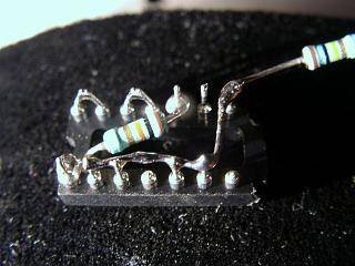
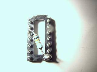
View of solder connections
Bend pins 1-2 3-4 and solder them together |
 |
 |
 |
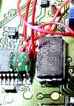
Gluing 74HC00 (DB = Dead bug)
Put IC in chip socket |
Verify the notches are on the same end |
|
|
Stick double sided tape and remove the excess with scissors! |
Gluing at a precise place ! |
 |
 |
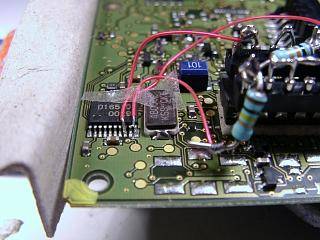
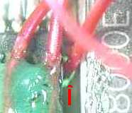
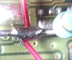
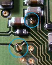
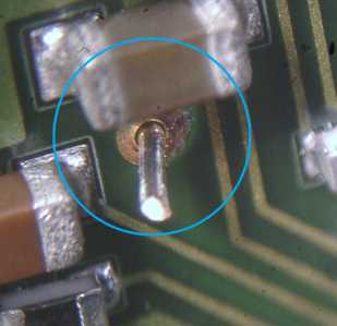
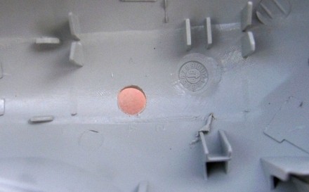
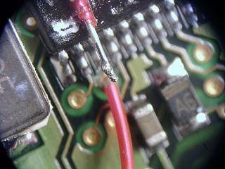
Passage and connection of a wire at pin 13 via
 |
Strip 5 mm at the two ends of a wire |
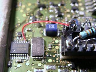 |
Connection between pin 8 of D16510 and pin 6 of DB
Solder one end to pin 6 of DB |
Position wire on pin 8 and maintain with scotch tape |
|
|
bend the end to follow pin 8 form, |
Solder by contact of the mini-drop with the soldering iron. Naturally one does not bring supplementary solder ! Then remove the adhesive tape |
|
|
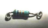
Connection betxween pin 10 of D16510 and 14 DB
via a 100Ko resistor
Prepare resistor with wire |
Solder resistor to pin 14 DB |
|
 |
Cut excess |
Solder the wire and leave an leave extra tail for later |
|
|
Adjust the wire and solder on pin 10 (always with mini drop). Solder without pushing! |
Put a big drop of glue to obtain a good stability |
|
|
Detail of glue protection |
|
|
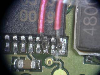
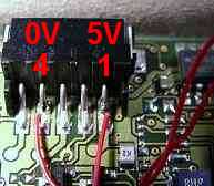
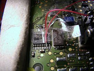
Take a little rest: The "easy" connections between USB and
DB
Put two wires of 5cm with a small hook at the USB connector |
Solder "ground" to pin 4 and 7-9 DB Solder +5v (red side on USB cable) and pin 14 DB |
|
|
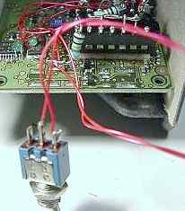
Adding a switch to change between
Vesta Pro normal mode and SC (long exposure) mode
PS : a new simplified approach using a phono jack is a capability:
No more switch: Axel Canicio has shown that only one wire from the PC parallel
port (pin 2) is needed!
The jack, with an internal cut switch will do all of the work of the external
switch!
Choose a small switch |
Pass a wire through the via connected to pin 10 and located between the two IC NOTE : see easier passage on new page with stereo jack !! |
|
|
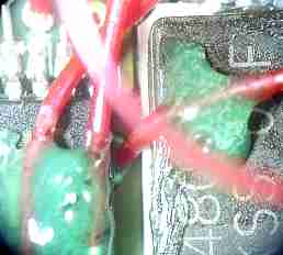
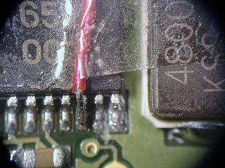
Overview after passing wire |
Bend a wire, insert it into the VIA, and fix it with a drop of hot glue |
|
|
Connect another wire to the tail of the 100Ko resistor |
Solder the wires to the switch, making sure that one is connected |
|
|
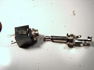
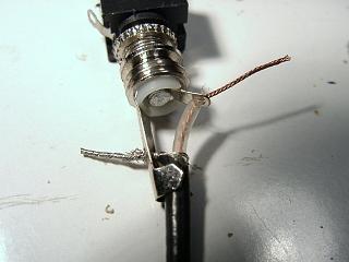
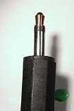
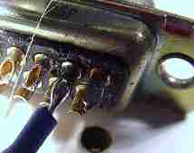
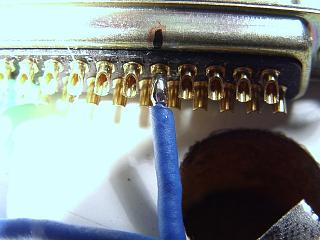
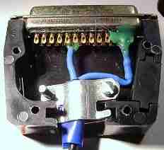
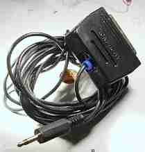
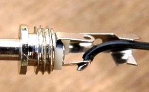
Preparation of the jack for connection to the signal
of the PC parallel port (Pin 2)
Note: I have just bought stereo jacks with a cut switch. It should make it possible to switch the connection to leg 10 when the male plug of the jack is inserted while also providing the signal coming from pin 2 of the parallel port of the PC, and thus to eliminate the need from a switch ! Later with only 2 of them side by side all the signals from PC parallel port pins 2, 3, 4 & 5 could be brought in to implement the other functions ! Testing to follow!
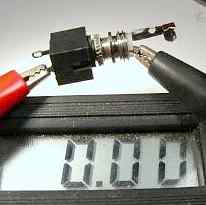
For the now (until testing of cut switch), you may still use a mono jack without the cut switch. Test with an ohm meter which corresponds with the connections between the thimbles of the jacks male and female connectors. A reading of 0.00 is the sign of a direct contact ! |
Shown with separate connections: the pin on the side of |
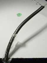
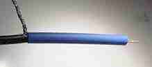
Strip then installation of a shielded wire 1 conductor and the braid. Length used at home = 4m |
|
|
|
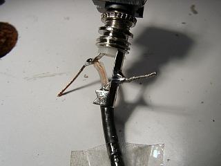
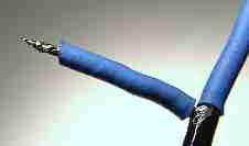
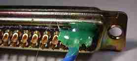
Soldering |
Cut off the extra ends of wire, tighten the small anti-tension prongs and install the cap |
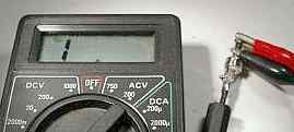
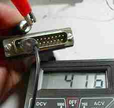
Check with the ohm meter that the welding of the braid (shield) did not damage
the transparent plastic sheath. 1 means infinite resistance, Good ! |
|
|
|
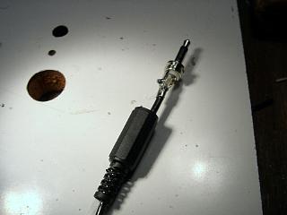
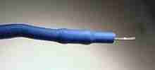
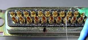
The male jack done. Red is signal |
Prepare the length of the wire for the parallel port PC connector. Stripping. You can use Scotch tape to hold the wire down while working with the wire |
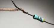
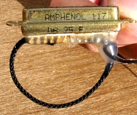
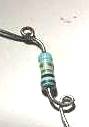
470 ohm resistors |
|
|
|
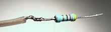
Prepare the resistor for a serial connection. Make two or three turns of stripped wire around the tail of the resistor |
Solder |
put an ad hoc length of heat-shrinkable sleeve |
|
|
|
Heat the sheath with the lighter (without excess) |
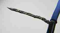
Twist the ground wire (shield). Put a little solder at end |
put an ad hoc length of heat-shrinkable sleeve |
|
|
|
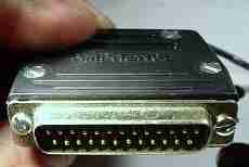
PC parallel port plug |
Position and solder the wire to the center of pin 2 |
Reinforce with hot glue |
image to come |
|
|
Look for pin 21 (ground) and mark with marker pen Note: I did not test this yet... but this connection seems useless because it is redundant with the ground of the USB connector. You can test without! |
If you use the ground connection, position the wire in the |
Solder |
|
|
|
Protect with hot glue... All done |
Install a protection cap |
Roll up a little Scotch tape for electrician to increase the thickness |
|
|
|
set up the plug and the accessory of security |
Close everything with screws |
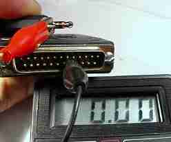
Test pin 21 and jack ground with the ohm meter. Check for shorts and good connections |
|
|
|
Test pin 2 and the red (tip) point of jack |
All done for the male part ! |
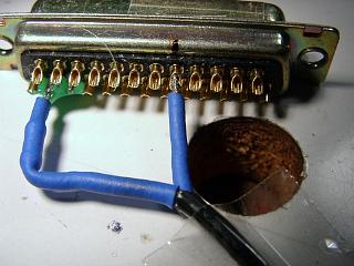
Studying the female plug |
|
|
|
Solder 2 wires, one black for ground, one white for signal |
Solder the white wire from pin 2 to 5 of DB |
The command signals wires for the PC parallel port is done! |
|
|
|
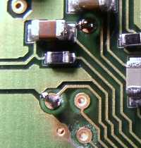
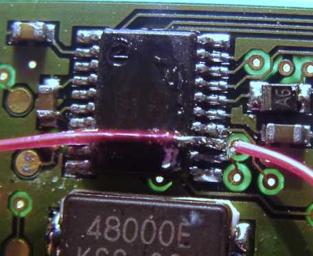
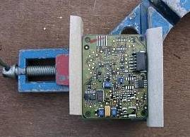
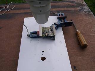
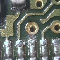
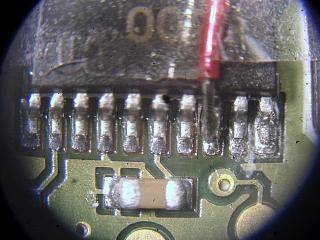
Now turn over the circuit board over and tighten it up at an angle of about 30°. Always use cardboard to protect it |
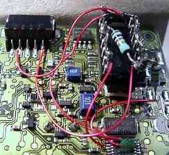
Overview of working zone |
For the two VIAs, cut the extra length of the wire sticking out 3mm left for soldering |
|
|
|
Scrap the varnish a little (be careful, it really should not be needed as
the solder will run inside the VIA). This shows the wire passed through the
VIA at pin 13 |
Same for via at pin 10 |
Final soldering complete! Clean the circuit with a compressed-air bulb to eliminate all droplets. All that remains is to check the assembly carefully under the magnifying glass to locate possible bridges of solder or bad connections |
|
|
|
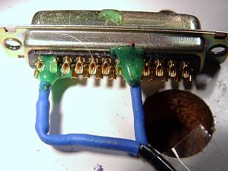
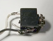
NEW VERSION with more simple link to PC
A lot more simple !! |
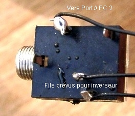
A FEMALE STEREO JACK + CUT |
Solder the wires of the standard mod to the pins at the bottom. The wire coming from 5 DB (was white) is soldered to thye upper pin. No more ground wire (black) needed ! |
|
Cut a 6mm hole at the place suggested here :
|
|
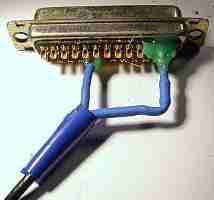
Introduce female jack taking care pins are away from Vesta circuitry ! |
|
Only one wire goes to PC // port pin 2. The other end is soldered to the pin shown at right (most in the center) ! When put into the female part, the Vesta will enter SC mode ! |
|
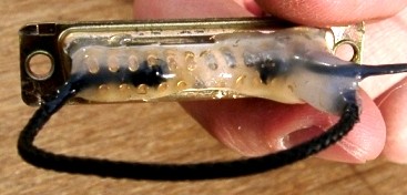
After soldering at pin 2, add a small nylon rope as shown. Add hot glue. |
|
The nylon rope is my last trick to pull easily off the connector after use ! |
|
Look at the final aspect ..clean, no ? |
|
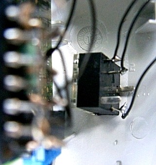
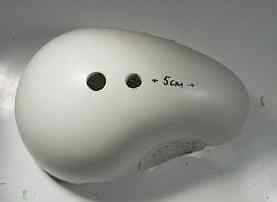
Drilling the case and completing the mod (old version)...
Drill the half of the shell with the label, drill the two holes as indicated with the diameter needed |
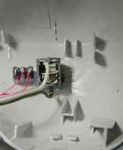
Place female jack and the switch |
After reconnecting the main PCB to the secondary PCB (CCD head) and the USB wire, place it carefully in the shell. Check that the new wires are not within proximity of the case spurs which could damage them during closing |
|
|
|
Don't forget the metal block with Kodak thread |
Close carefully |
All Done ! |
|
 |
Welcome to the world of the VP-SC users! |
Miscelleanous
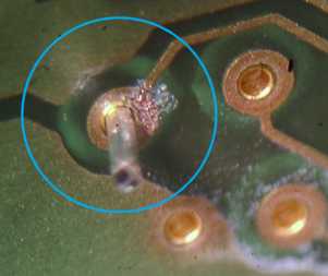
1) Solder a leg !
A stress free method I just made up for this mod !
It gives a clean result without much risk of making annoying solder bridges
A binocular is recommended but your cheap 3 dioptry glasses are Ok.
Strip a length of 30 gauge wrapping wire for about 5mm at both ends.
Solder one end on the ad hoc pin of the LS7400 socket.
Now cut the free one to leave only 1.5mm unstripped at the other end. Use
small cissors to do it !
Hold the wire steady with a "third hand" tool or scotch tape.
Put fresh solder in contact whith the wire and touch it with the soldering
iron whitout touching the wire.
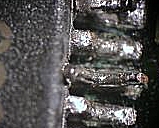
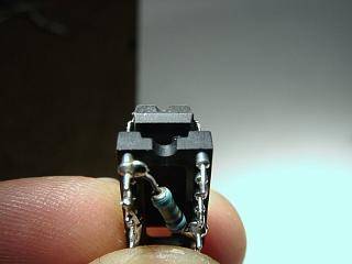
The solder melts and a droplet forms on the colder wire (see pic below)
Gluing and soldering the wire on IC
The best glue to use is hot glue. Hold the wire with scotch tape on the IC
while leaving the outstretched bare end above the leg and hanging over the
IC.
Use a drop of melted glue to secure in place
After the glue has hardened, bend the end of the wire towards the
bottom
(note in the case of a lifted leg like at pin 10, just use slight contact)
and push rather firmly the end of the wire in between two legs of the IC.
Then pull it back a little and push it sideways to have it in good contact
with the leg.
Clean the point of the iron with fresh solder and shake once to remove
excess.
Come in contact with the wire while holding the iron with both hands
then avoiding hand shake and working stressfree !
The solder minidrop around the wire melts instantly a gives a shining perfect
soldering !
2) A leg is accidentally broken just
outside the IC,
Do I have to buy another Vesta ? No ! just fix it
!
Dig into the IC black material with thin jewelry pliers above the broken
leg
in order to make about 1mm of copper appear.
Apply fresh solder to the soldering iron. Take a few cm of wrapping
wire.
Strip a couple mm and dive it in the solder.
Pull and leave a droplet at end. Put it at 45° between pad and IC freshly
uncovered copper.
Hold wire with scotch tape on the PCB. Touch breafly with soldering iron
hold with both hands.
Cut excess wire with iridectomy scissors or small cutter blade.
Images et textes copyright S. WEILLER, 2001-2010


 s
s